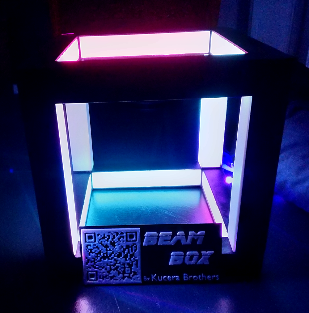
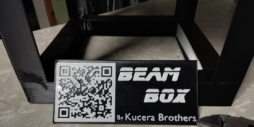
Beam Box
CodeMash
Thanks for scanning the QR Code! My brother and I designed and modeled this "Beam Box" to play with combining 3d printing and LED lights. The goal was to make a conversation/art piece that would be modern and fun. The name came from the idea of having a beam racing around in a box.
We finished this just in time for CodeMash, but we're considering uploading the files later. If we do upload them, I'll update this post with a link to them, so keep this page bookmarked if you're curious.
This was predominantly a pairing project between my brother and I. If you'd like to hear more about pairing, attend my "Pairing: From Pain to Profit" talk Friday at 4pm!
If you're curious to hear more about how we created the project, the mistakes we made and lessons we learned, read on!
Vision and Definitions
I've always enjoyed messing around in Blender, though I've never been really good at 3d modelling, or really anything that requires spatial skills. I bought a printer last November and have been using it as an excuse to learn more about modelling. I watched a great 35 part course on precision modelling that really helped me understand how to be more precise in my models. (There is a lot of self promotion / recap, but using youtube's 1.5x and skipping intros, it was super informative).
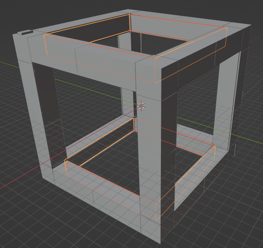
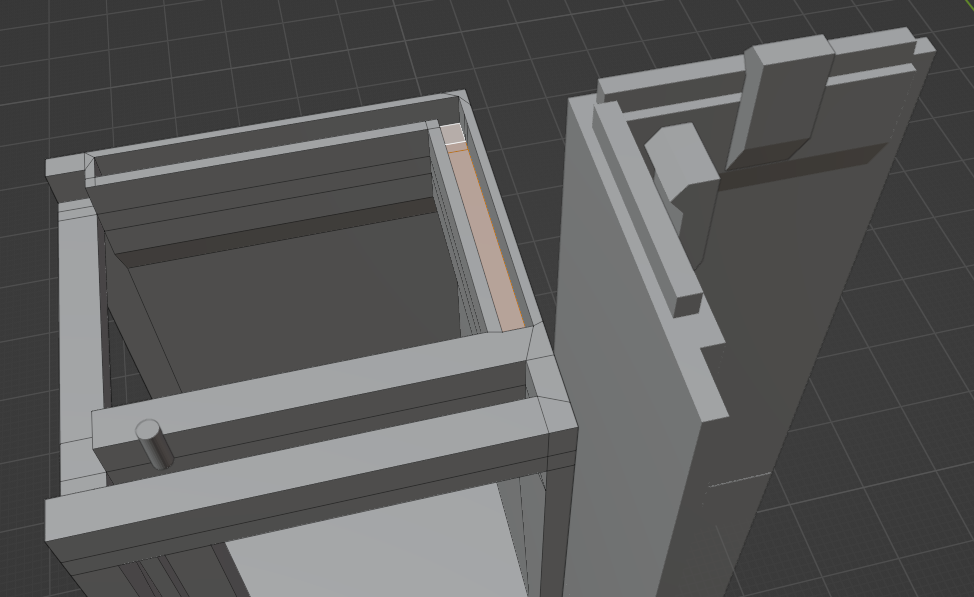
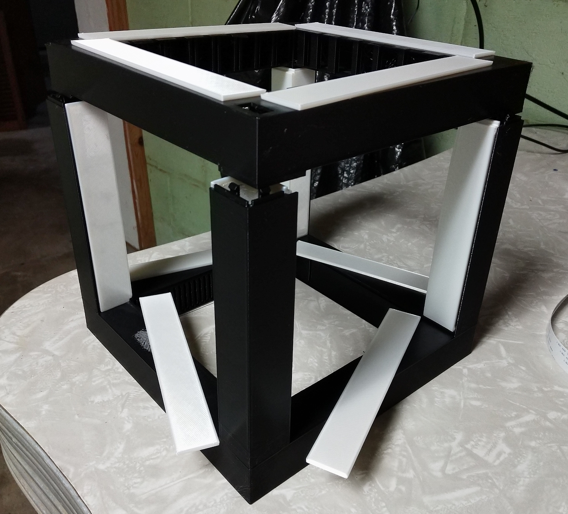
When talking with my brother about printing ideas, he came up with the concept for a "Beam Box": a "black cube whose inner walls are diffused led lights". With that vision, we spent a number of nights together modelling the cube and thinking through how we could make it printable and constructible.
We started with the Blender starter cube, and then made guesses as to how large the holes should be, how large the tubes should be, and how we'd insert the diffusers. We wanted to create something that could be assembled and reasonably dissembled, so that it was easier to insert or change the light strips. At the same time we wanted something sturdy enough to "pass the shake test" where we pick the cube up and shake it. If it fell apart, it wasn't robust enough; we didn't want someone bumping into it and it falling apart.
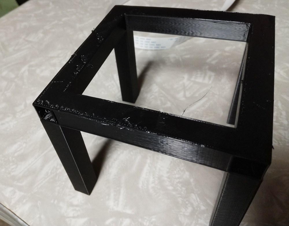
We started by measuring the exact width of the led light strip, and then making tubes that were just a hair wider. We knew we needed to thread them through somehow, so we made holes in the corners for feeding. Before going any further, we went ahead and printed the bottom ring and the four pillars for scale. (The top ring would need to be printed separately because its essentially all overhangs. This scale model was super small, but it gave us something both to conceptualize size, as well as to be able to talk through design ideas without having to draw or model an idea. We could pick up, rotate, and point to the model. (I think this speaks to how important prototyping is, regardless of your field; it's so fun to see software principles like 'thin vertical slice' and 'iteration' be relevant in other fields.)
Before I go further, it'd be good to define some terms, both from 3d printing and part names we came up with.
3d Printing Terms
| Term | Definition |
|---|---|
| Skirt | A small square outline around your print space |
| Brim | When printing something tall and thin, you usually want a brim. This is a thin layer of plastic around the base of your print. This gives you more surface area so the vertical print doesn't shift or fall over during printing. Then you just rip it off the bottom of your piece after the print is done. |
| Stringing | This comes in a light form, that looks like fuzz or small hair, or it can be full on the width of your filament, where the plastic didn't stick to the base or rest of your model. |
| Overhang | When the printer is printing over nothing. You can't print on thin air! If you do, you'll get extreme stringing, which at its worst means a ball of plastic yarn. I find these get worse if you make a turn while in mid air. |
| Supports | Supports are temporary parts of the print that hold up overhangs so you don't get stringing. Then you rip them out at the end. |
| Bridging | You can print over surprisingly large gaps if both ends of the gap have something to connect to. This looks like you're making a bridge from one side to another. Bridges that are too long will lead to stringing or the plastic sagging. |
| Slicing | Taking a 3d model and slicing it into printable layers. I used Prusa Slicer. |
Beam Box Part Naming
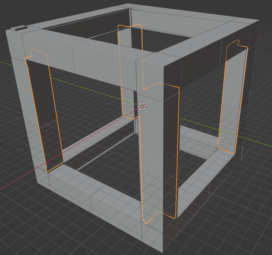
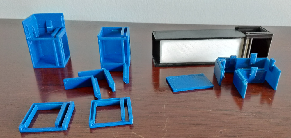
Tube
Horizontal tubes that the leds run through. These are black and prevent light from shining through.
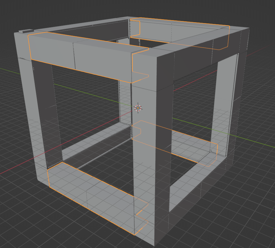
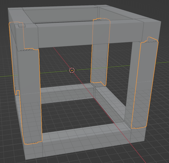
Pillar
Vertical tubes. Slightly different from horizontal tubes because they have clasps to connect rings, and they have L shaped diffusers.
Diffuser
Thinner white walls that diffuse the light / glow.
L Diffuser
An L shaped diffuser that is used to provide light for the pillars.
Corner
Corners are where a lot of the complexity rest, as the diffusers and pillars snap into them.
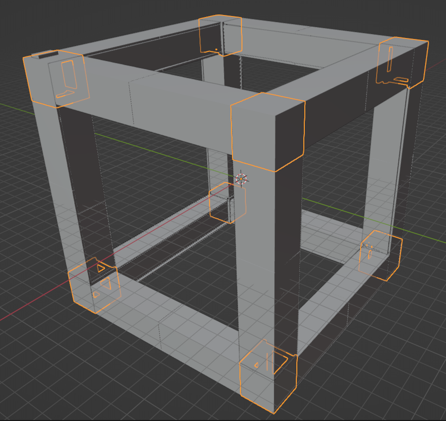
Clasp
Pillars uses these to clasp onto the corner for a firm fit. They're connected to pillars and the corners have a matching indent. Also pictured are the inset bumps on the pillar that sheath into matching slots in the bottom of the corners.
Insets / Slots
Pillars used an insets that fit into a slot in the corner. This acted as a 'backboard' for the clasp, so that the clasp was forced into its slot by the inset pushing on the slot. (In the pic the corner is upside down on the left with its slots. The pillar is on the right with its insets).
Ring
Our reference for corners plus tubes. Essentially one square.
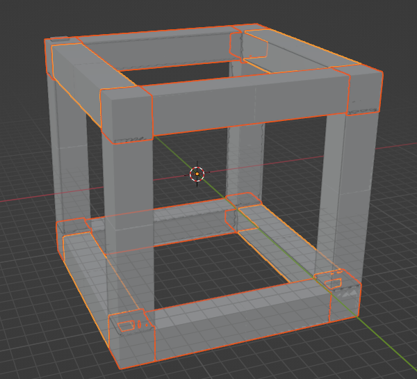
Base
We printed one ring with all 4 pillars built in so we didn't have to snap them in or worry about printing double-sided pillars.
Process
Initial Scaling
Printing the initial scale made us realize we wanted to make the box a lot bigger. We also realized that we wanted the diffuser panes to 'slide' into the tubes. We initially considered more complex designs, but we found that sliding the plate down through snug slot in the corner was enough to keep the diffuser in, even in an upside down 'shake test'. We did eventually decide to replace the slide down with a 'bend in the middle and slide into corners' as that kept the snug fit, made things more symmetric, and helped with printing.
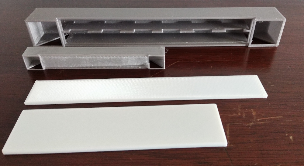
After work on the tube and a first pass on diffuser inserts and corners, we scaled up to do a 'hot spot' test. This was done to see if the light was even on the diffuser or if it made concentrated patches of light and dark. We also wanted to test the tube walls and make sure light only came from the diffuser. Our initial test (the larger gray tube below) with gray plastic found the walls to be too thin. As seen in the tube, we planned to do an inner support wall for the LEDs to run along, but we removed it for later iterations (which helped a lot with hot spots).
We also tried scaling up a second time by 1.5x. The large white rectangle below is half a diffuser at 1.5x. At that scale I couldn't print a single tube all in one piece; it would be too big for the printer, and use a lot of plastic. So we kept the original scale. (Technically we chopped off 2cm because I had misread my rectangle print bed as square and used the larger side).
Connecting the Pieces
The next chapter was spent in honing in how to snap all the printed pieces together, and focused on the corner. We went through a lot of iterations figuring out how to connect the diffusers and pillars to the corners. This challenge essentially centered around a number of core concepts:
-
how snug is properly snug,
-
how much force is robust but easy to assemble,
-
how do you meet the above goals while being printable? (handle overhangs)
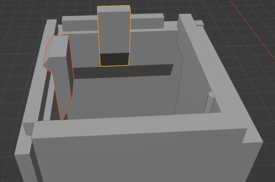
Most of the time that I thought I needed more complicated design than friction fit, I was wrong. The challenge mainly revolved around accounting for printer tolerance to get something snug without needing major force to fit together. Initially I added clasps, and while they worked great in the one piece corner test, we found they were too hard to attach when we had four corners to all connect, all of which were applying forces to each other. The L diffusers slid into the corners, but they were too loose to stay in for a shake test. I could (and probably should) have gently tweaked the width of the inset/gap, but instead I added a small nub that let me 'click in' the part and stay secure.
It was really fun to realize I could print less and less material while still testing connection points. As I tried more variants (each part in the pic below is unique and a different attempt) I realized I only needed enough to represent the connection point, which saved me both material and time. I came to think of it as doing 'unit tests' for printing.
Once I was happy with my unit tests, I printed the black and white piece, which was a single corner and half a tube. This let me test my latest version of the pillar and L diffuser connections, as well as do an at-scale light test, while still not printing a whole tube.
CodeMash Plaque
When we realized we'd have it done in time for CodeMash, I came up with a plaque that people could scan to read more about our project! The trickiest part was creating the QR code. I found an online generator for the image, and the imported it into blender as an image plane. I then used a Displace modifier to push white up and black down. This was really tricky in that to get the resolution right I had to subdivide the plane a huge number of times, which made blender slow. Once I had it though, I was able to use the boolean modify to 'stamp' it onto a plane cube, and then use 'Limited Dissolve' to make the mesh have probably 1/100th of the original vertices. Then it was just a simple two color print. Black background, white lettering and qr code. I also "Ironed" the letters and qr code to make them more smooth. I'm really happy with how well it came out and how easy it was to scan the code in my tests. (Hopefully it was easy for you too!).
Mistakes We Made
The first scale ring I didn't use enough supports, and so we had a number of imperfections and some serious internal stringing. Later prints I used supports for the entire upper lip of the tubes.
We didn't use enough glue on the bed for that ring either, and so had some external boils and imperfections. Future prints I made sure to have a layer of glue before any large prints.
A couple times I missed smaller parts (like the nub on the L diffusers, or clamps) when printing. Throughout the iterations I got more careful about doing thorough reviews while slicing the model.
Where the pillars connect to the corners, we have an inset and sleeve pattern, which I like. However the spaces weren't symmetric and because of being on a corner, it was hard to get them to snap in, especially when you had three other pillars that needed to go in and not much flex. This proved to be a pain.
I used clamps to make the corner-pillar connection snug. The hope was to pass a shake test without glue. This was overkill and while a single corner (unit test) was easy to connect, connecting all four corners (integration test) didn't work at all with the clamps. There just wasn't enough give. Turns out, snapping off the clamps and just gluing the sleeves/insets was much easier.
As mentioned above, a sign of our immature design was how hard it was to get things to snap together (moderate) and how much harder it was to remove those pieces. For instance, getting the diffusers in was much easier than removing them to start inserting the lights / led tubes.
Speaking of inserting lights, it was hard to feed all the wire in. Having wider tubes would have given us more thumb room for positioning.
What We Learned
Measure Once, print twice. For real. The material is cheap if you're doing small parts, and no amount of wrestling in blender will be as good as seeing the real thing. This feels similar to a TDD / agile approach where no amount of up front documentation will prepare you for reality. It's also much easier to reason about something you can hold in your hand.
Print Minimum. If you're going to follow the above rule (or even if you don't) you want to print the minimum you can for each iteration and test. This saves you money (usually measured in cents, not dollars), but more importantly it saves you time.
Blender CAD is pretty cool. I had fun going through the tutorials and even more trying to actually build something with my new knowledge. It helped move those skills into longer term memory / muscle memory, and I could feel my design abilities grow while using it. Being able to snap to specific points and build with mm precision is really neat, and I'm excited to see what I can apply this knowledge to next.
Mirror Modifiers are fun. Mirror (and boolean) modifiers are really powerful, and let me design one part of the cube, and then just mirror it to all the other parts. This let me worry about one correct design, and not how I'd duplicate it elsewhere. Mirror and Boolean (subtract one piece from another, used for clasps and nubs) are comparatively simple to learn, but can be combined in powerful ways.
Snug is great. We spent time over designing connections before realizing how powerful friction alone can be when used correctly.
Watch out for overhangs. A lot of time was spent figuring out how to make a design printable, where overhangs didn't distort it. Using print supports helped a lot, but connections couldn't take the distortion of 'residue' that's left behind when removing supports. For those we really had to think about how we could use slopes or angles to remove overhangs. This was surprisingly fun, as it made the design feel like solving a puzzle.
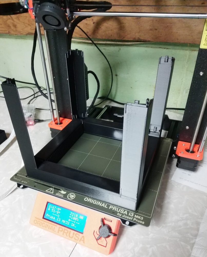
Print Modular. Doing a 13 hour base print was terrifying. I was so concerned it'd go bad 9 hours in. If I were to do this again I'd figure out how to print the pillars separately (double sided) so that the largest print is just a single base.
 Website